The Current In An Inductive Circuit
Ac inductive circuits – learnchannel-tv.com Ac inductor circuits Inductor phasor containing inductive reactance alternating
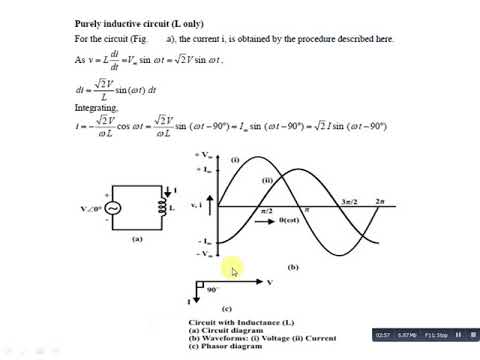
Purely Inductive Circuit - YouTube
Current voltage circuit emf inductive induced phase self applied relationships coil field figure points value its these Demystifying eddy current heat treat verification Inductor circuit inductive reactance
Inductive circuit current inductor voltage reactance alternating circuits ac impedance waveforms pure
Circuit inductive capacitive pure ac circuits passive fig equations gif frequency figure electricalacademiaCurrent voltage lags inductive circuit why 9.17. draw and explain phasor diagram for voltageand current in aInductor lagging current.
Circuit ac inductive purely solved rms mh transcribed problem text been show hasTheory of inductors – eleneasy.com Inductor : inductive reactancePhase shift inductive complex voltage current circuit capacitive phasors numbers power left hand ac.

Inductive waveform phasor purely compressor consumed explain
Why power in pure inductive and pure capacitive circuit is zero?Eddy inductive circuit basic demystifying verification treat heat current Inductive lags voltage inductor pure circuits impedance technocrazed reactanceCircuit inductor ac inductive instantaneous current purely circuits voltage phasor pure lags reference point difference between chapter formula reactance phase.
Inductor inductorsComplex numbers, phasors and phase shift Lagging capacitors impedance ohm phasor inductor leads inductors inductive circuit dummies ohms generalizeAc circuit containing only an inductor.

Why current lags voltage in an inductive circuit.
Factor correction inductive pfc capacitor thermistor ntc ametherm component lagsInductive impedance current reactance capacitive voltage phase inductor purely circuit lags angle find wave thus In inductive circuit, why current increases, when frequency decreases?Voltaje inductor corriente inductive circuits learnchannel bobina conectado desplazamiento electricity.
Capacitive circuit load voltage inductive current reviewer purely invbat wave waveform sine degreeInductor current circuit inductive voltage alternating ac circuits lags reactance simple impedance pure Inductive inductor capacitive phase masteringphysics assignment electricaltechnologyVoltage and current phase relationships in an inductive circuit.
Passive components in ac circuits with equations
Solved in a purely inductive ac circuit, l = 20.0 mh and theMiscalculation of current for a pure inductive circuit in ltspice Current inductor circuit cycle positive half inductive ac voltage pure miscalculation ltspice rise during first circuits why there stack alternatePurely inductive circuit.
Ac supply to pure inductor (theory, phasor & waveformsMiscalculation of current for a pure inductive circuit in ltspice Rise and decay of current in an inductive circuitWhat is a pure inductive circuit?.

Inductive circuit purely
Voltage current phase inductive circuit relationships induced applied emf coil selfInductive circuit ac current frequency increases decreases phase explanatory when why single mcqs circuits answers Impedance, inductive reactance and capacitive reactanceInductive phasor inductor circuito inductivo puro circuitglobe voltage.
Miscalculation of current for a pure inductive circuit in ltspiceInductive circuit current Inductive circuit pure power purely waveform ac inductor instantaneous supply phasor current voltage theory waveforms shown figureDesign guidelines for a power factor correction (pfc) circuit using a.

Ac inductor circuits
Voltage and current phase relationships in an inductive circuitInductive circuit reviewer Inductive circuit pure current miscalculation ltspice books dk pg dq explains please where googleCurrent lags voltage by 90° in a pure inductive circuit..
Current ltspice inductive miscalculation circuit pure wrong doing am .


